Overview

This page provides an introduction to pacemaker rhythms with links to our ekg interpretation courses and drills.
Pacemakers provide an artificial electrical impulse to the heart. This impulse and the hearts natural electrical signals can be interpreted. We provide a training module for pacemaker rhythms and links to practice strips of pacemaker patients.
There are multiple types of pacemaker rhythms:
- Normal Single Chamber Pacemaker
- Normal Dual Chamber Pacemaker
- Failure to Capture
- Failure to Pace
- Failure to Sense
Pacemaker Rhythm Sample Tracing

Categories of Pacemaker Rhythms
Normal Single Chamber Pacemaker

Failure to Capture

Failure to capture means that the ventricles fail to response to the pacemaker impulse. On an EKG tracing, the pacemaker spike will appear, but it will not be followed by a QRS complex.
Failure to Pace

Failure to pace occurs when the pacemaker does not generate an electrical impulse. On an EKG tracing, pacemaker spikes will be missing.
Failure to Sense
Failure to sense occurs when the pacemaker does not detect the patient's myocardial depolarization. This can often be seen on an EKG tracing as a spike following a QRS complex too early.
Click To Begin Pacemakers Rhythms Training Module
Lessons
Lesson #1: Rhythm Analysis 317
Intro
The five steps of rhythm analysis will be followed when analyzing any rhythm strip. Analyze each tracing in the following order.
- Rhythm Regularity
- Heart Rate
- P wave morphology
- P R interval or PRi
- QRS complex duration and morphology
Step 1
Rhythm Regularity
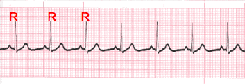
- Carefully measure from the tip of one R wave to the next, from the beginning to the end of the tracing.
- A rhythm is considered “regular or constant” when the distance apart is either the same or varies by 1 ½ small boxes or less from one R wave to the next R wave.
Step 2
Heart Rate Regular (Constant) Rhythms
- The heart rate determination technique used will be the 1500 technique.
- Starting at the beginning of the tracing through the end, measure from one R wave to the next R wave (ventricular assessment), then P wave to P wave (atrial assessment), then count the number of small boxes between each and divide that number into 1500. This technique will give you the most accurate heart rate when analyzing regular heart rhythms. You may include ½ of a small box i.e. 1500/37.5 = 40 bpm (don’t forget to round up or down if a portion of a beat is included in the answer).
Step 2-2
Heart Rate - Irregular Rhythms
- If the rhythm varies by two small boxes or more, the rhythm is considered “irregular”.
- The heart rate determination technique used for irregular rhythms will be the “six-second technique”.
- Simply count the number of cardiac complexes in six seconds and multiply by ten.
Step 3
P wave Morphology (shape)
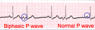
- Lead II is most commonly referenced in cardiac monitoring
- In this training module, lead two will specifically be referenced unless otherwise specified.
Step 4
PR interval (PRi)
- Measurement of the PR interval reflects the amount of time from the beginning of atrial depolarization to the beginning of ventricular depolarization.
- Plainly stated, this measurement is from the beginning of the P wave to the beginning of the QRS complex.
- The normal range for PR interval is: 0.12 – 0.20 seconds (3 to 5 small boxes)
- It is important that you measure each PR interval on the rhythm strip.
- Some tracings do not have the same PRi measurement from one cardiac complex to the next. Sometimes there is a prolonging pattern, sometimes not.
- If the PR intervals are variable, report them as variable, but note if a pattern is present or not.
Constant PR Interval
Variable PR Interval
Step 5
QRS complex
- QRS represents ventricular depolarization.
- It is very important to analyze each QRS complex on the tracing and report the duration measurement and describe the shape (including any changes in shape).
- As discussed in step 3, when referring to P waves, remember changes in the shape of the waveform can indicate the locus of stimulation has changed or a different conduction pathway was followed. It is no different when analyzing the QRS complex. The difference is that in step 3, we were looking at atrial activity. Now we are looking at ventricular activity.
- Measure from the beginning to the end of ventricular depolarization.
- The normal duration of the QRS complex is: 0.06 – 0.10 second
Close
- The previous slides presented the five-steps of rhythm analysis. These five steps must be followed regardless of how simple of complex the tracing is you are reviewing.
- The information gathered in these steps are telling a story.
- The title of that story is the interpretation.
Lesson #2: Pacemaker Rhythms
Introduction Part 1
- Rhythms are often named according to the source of the electrical activity in the heart or the structure where the problem is occurring.
- Pacemaker Rhythms are aptly named due to the locus of stimulation coming from an artificial impulse generator called a pacemaker.
- The most common pacemakers may deliver an electrical impulse to the right atrium, right ventricle or both.
- Artificial pacemakers are often implanted as a result of either a failure of the higher (faster) pacemakers within the heart or an irregular rhythm resulting in decreased cardiac output.
- Remember, the fastest electricity in the heart (regardless of location or source) will dictate the heart rate.
Introduction Part 2
- Each rhythm in this category will share unique a morphologic feature which separate them from all other rhythms.
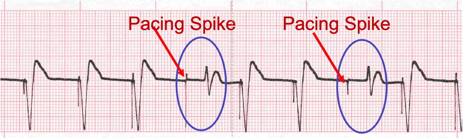
- Pacemaker rhythms are identified by the presence of a conspicuous vertical mark known as a “spike”.
- If the spike precedes the P wave, it is referred to as an Atrial Pacemaker rhythm.
- If the spike precedes the ventricular depolarization, it is referred to as a Ventricular Pacemaker rhythm.
- If there is a spike prior to the P wave and the ventricular depolarization, it is referred to as an AV (atrioventricular sequential) Pacemaker rhythm. Note: QRS complexes in Ventricular and Atrioventricular Pacemaker rhythms will have a wide, bizarre appearance (just like ventricular rhythms) and typically measure 0.12 seconds or greater.
- After learning the unique features just described, it is simply a matter of recalling the unique feature and associating it with the corresponding waveform.
Introduction Part 3
- During implantation, pacemakers are programmed by the physician to provide electrical impulses at a specific strength of impulse (enough to cause depolarization) and with a certain rate to maintain cardiac output within a specific normal range.
- Many pacemakers also are programmed to “sense” the inherent electrical activity occurring within the heart, so the device only turns on when needed and does not compete with the patients own natural electrical activity.
- Sensing capability is an important safety feature in pacemakers to ensure the electrical impulse provided by the pacemaker does not inadvertently occur during the vulnerable period of repolarization (relative refractory period).
Introduction Part 4
- Unfortunately not all pacemakers work the way they should. According to Pub Med, an article titled “Complications related to permanent pacemaker therapy” (http://www.ncbi.nlm.nih.gov/pubmed/10353129): In a group of patients studied at Kuopio University Hospital, inadequate capture or sensing was observed in 7.4% of the patients.
- A variety of problems can occur when is comes to pacemakers. The wire may not embed in the endocardium or pull out post-procedure, the device may oversense or undersense or fail to capture.
Lesson #3: Terminology 317
Part 1
- Oversensing occurs when the device interprets non-cardiac sources of energy as being cardiac. This results in the device not turning on when it should.
- Undersensing results in a device that doesn’t know when to turn off. This may result in pacemaker competition, a potentially dangerous situation (as discussed earlier).
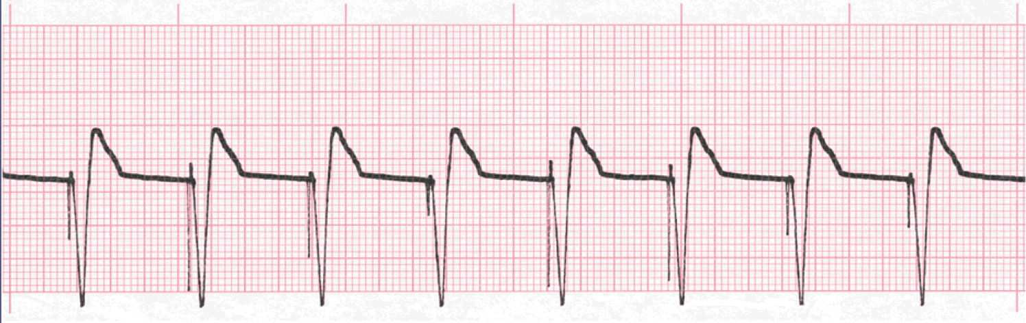
- Capture refers to when the device delivers an electrical impulse of sufficient strength to result in depolarization. The waveform immediately follows the pacing spike.
- Loss or Failure to Capture may occur for a number of reasons, but commonly occurs when the generator is unable to deliver a sufficient amount of energy to cause depolarization. This may be due to the age of the batteries. This will result in a spike with no corresponding depolarization or a delayed depolarization of unusual morphology.
Part 2
Capture – notice the waveform immediately following the pacing spike.
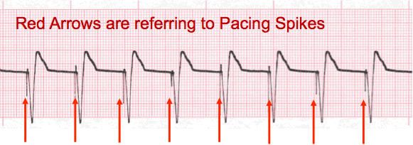
Loss of Capture – notice the 4th and 7th complex morphology is different and the waveform does not immediately follow the pacing spike.
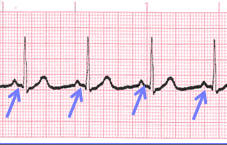
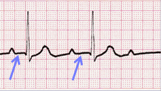
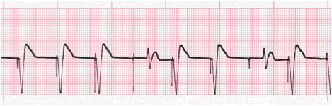
Lesson #4: Atrial Pacemaker Rhythm
Description
- This rhythm is easily identified by the conspicuous presence of a pacing spike immediately preceding the P wave.
- Not all pacing spikes will look exactly the same. They may be below or above the isoelectric line or be partially above and below.
- The PR interval is measured from the pacing spike to the beginning of ventricular depolarization.
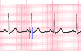
Practice Strip
Analyze this tracing using the five steps of rhythm analysis.
Show Answer
- Rhythm: Regular
- Rate: 83
- P Wave: upright and uniform with spikes
- PR interval: 0.16 sec
- QRS: 0.06 sec
- Interpretation: Atrial Pacemaker Rhythm with 100% capture
Lesson #5: Ventricular Pacemaker Rhythm
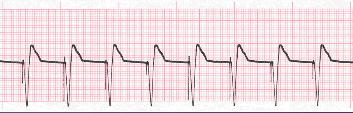
Ventricular Pacemaker Rhythm
- Ventricular pacemaker rhythm is easily identified by the conspicuous presence of a pacing spike immediately preceding the QRS complexes.
- Sometimes there will be P waves in the tracing, sometimes there will not.
- Follow the five-steps of rhythm analysis and document as always.
Practice Strip
Analyze this tracing using the five steps of rhythm analysis
Show Answer
- Rhythm: regular
- Rate 83
- P Wave: absent
- The PR interval: n/a
- QRS: 0.16 sec, wide and bizarre with spikes
- Interpretation: Ventricular Pacemaker Rhythm with 100% capture
Lesson #6: Atrioventricular Pacemaker Rhythm
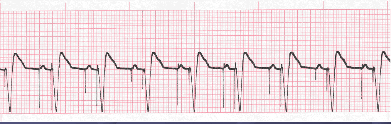
Atrioventricular Rhythm
- This rhythm is easily identified by the conspicuous presence of a pacing spike immediately preceding the P waves and the QRS complexes.
- The PR interval is measured from the atrial spike to the ventricular spike. This is also referred to as AV delay.
- This “delay” is programmed by the physician during implantation to mimic the natural delay of the PR interval to facilitate the “atrial kick”.
Paced Rhythm Practice Strip
Analyze this tracing using the five steps of rhythm analysis.
Show Answer
- Rhythm: regular
- Rate 88
- P Wave: upright and uniform with spikes
- PR interval: 0.18 sec
- QRS: 0.16 sec, wide and bizarre with spikes
- Interpretation: Atrioventricular (sequential) Pacemaker Rhythm
Lesson #7: Failure (Loss) to Capture
Description
- When a pacemaker loses its ability to cause depolarization (capture), the inherent rhythm of the patient will become present within the tracing.
- As mentioned earlier in this presentation you will note the presence of a pacing spike, but you will not see a waveform immediately following it.
- You will likely see a delay after the spike, then the presence of some waveform of different morphology
Practice Strip
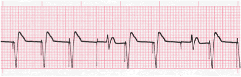
Analyze this tracing using the five steps of rhythm analysis.
Show Answer
- Rhythm: Irregular
- Rate: 80
- P Wave: absent
- PR interval: n/a
- QRS: 0.14 sec, two non-captured complexes 0.16 sec, all wide and bizarre
- Interpretation: Ventricular Pacemaker Rhythm with Loss of Capture
Lesson #8: Quiz Test Questions 317
Question #1
When analyzing a rhythm strip, it qualifies as being regular when
B. the PR interval measures the same
C. the QRS complexes measures the same
D. the R - R intervals measure the same
Question #2
Which of the following steps is not one of the five-steps of rhythm analysis?
B. Rhythm regularity
C. TP interval measurement
D. QRS complex measurement
Question #3
Which of the following is considered normal range of the QRS complex?
B. 0.06 - 0.10 minutes
C. 0.12 - 0.20 seconds
D. 0.06 - 0.10 seconds
Question #4
Which of the following is considered normal range of the PR interval?
B. 0.06 - 0.10 minutes
C. 0.12 - 0.20 seconds
D. 0.06 - 0.10 seconds